Internship Experiences
Propulsion Intern at NASA Dryden Flight Research Center
Worked: January 2011 to July 2011
Duties/Job Tasks
Jet Engine Modeling
Used NASA Glenn Research Center developed C-MAPSS40k to predict performance of C-17 Pratt & Whitney engines for different flight conditions. C-MAPSS40k is a generic turbofan engine MATLAB Simulink program in the 40,000 lbs thrust class. The Simulink model had to be modified to run certain flight conditions based on Engine Pressure Ratio (EPR) and Variable Bleed Valve commands. Was able to determine what levels of EPR command/ N1 Command the P&W engines could be ran to before "red-lining" the engines at different ambient conditions which could potentially destroy the engines.
Used NASA Glenn Research Center developed C-MAPSS40k to predict performance of C-17 Pratt & Whitney engines for different flight conditions. C-MAPSS40k is a generic turbofan engine MATLAB Simulink program in the 40,000 lbs thrust class. The Simulink model had to be modified to run certain flight conditions based on Engine Pressure Ratio (EPR) and Variable Bleed Valve commands. Was able to determine what levels of EPR command/ N1 Command the P&W engines could be ran to before "red-lining" the engines at different ambient conditions which could potentially destroy the engines.
Image Processing using MATLAB
Wrote two different programs to track and determine C-17 engine displacement during a ground test for safety requirements. The programs were written in MATLAB which also utilized the image processing toolbox in MATLAB. Open CV was an alternative to using MATLAB but with little time to learn new program MATLAB was an easy choice.
1) Automated image tracker - this program was designed to track a section of the C-17 engine(each section required code calibration) and determine the distances/rotations moved during the video. Several tests prior to the actual C-17 ground test showed that the program would work and achieve a high level of accuracy. Due to some last minute changes to our test procedure and video camera placements for the ground test the program was never used to determine displacements due to time it would take to re-calibrate the code.
2) User-Defined image tracker- This program used most of the code from the automated program but required the user to select the area of interest to track in each frame. Much time was spent to make this program as time efficient as possible in order to cut down on run-time. This program was very successful in determining accurate displacements and rotations of anything the user requested. Some benefits of the program was there was no need to calibrate the code for different areas of tracking. It can be used by others with little experience in image processing, and is easier to validate the accuracy of the results.
_________________________________________________________________________________________________________________
Aeromechanics Intern at NASA Ames Research Facility
Worked : September 2010 to December 2010
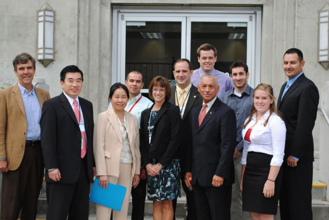
Green Aviation Conference at NASA Ames: in picture NASA Administrator Charles Bolden and Associate Administrator of Aeronautics Jaiwon Shin
Duties & Tasks
Analyze & Simulate rotary-decelerator during different phases of earth re-entry
A rotary decelerator is a re-entry vehicle that employs rotor blades to help slow the vehicle down during the descent instead of conventional parachute. The goal was to better understand key aeromechanics phenomena at different aspects of an earth re-entry. Estimations of vehicle descent rates after blade deployment and stability were the key goals to try and be obtained from simulations. MATLAB/Simulink were used for all simulations. For fun a Autodesk 3ds Max Simulation was created to demonstrate the flight profile.
Autodesk 3ds Max Video showing different phases of reentry of a rotary decelerator
